

Before any build log, here's a video:
That was a Rubik's cube being solved in 0.38 seconds. The time is from the moment the keypress is registered on the computer, to when the last face is flipped. It includes image capture and computation time, as well as actually moving the cube. The motion time is ~335 ms, and the remaining time image acquisition and computation. For reference, the current world record is/was 0.637 seconds.
The machine can definitely go faster, but the tuning process is really time consuming since debugging needs to be done with the high speed camera, and mistakes often break the cube or blow up FETs. Looking at the high-speed video, each 90 degree move takes ~10 ms, but the machine is actually only doing a move every ~15 ms. For the time being, Jared and I have both lost interest in playing the tuning game, but we might come back to it eventually and shave off another 100 ms or so.
The machine can definitely go faster, but the tuning process is really time consuming since debugging needs to be done with the high speed camera, and mistakes often break the cube or blow up FETs. Looking at the high-speed video, each 90 degree move takes ~10 ms, but the machine is actually only doing a move every ~15 ms. For the time being, Jared and I have both lost interest in playing the tuning game, but we might come back to it eventually and shave off another 100 ms or so.
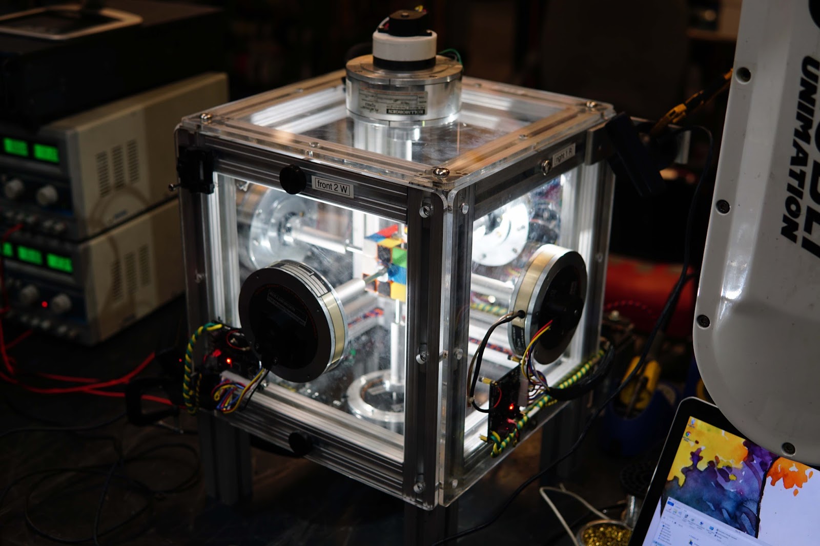
Here's the contraption:
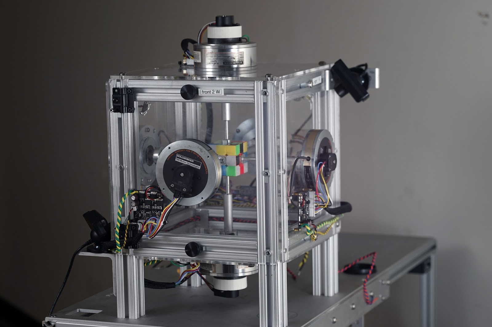

The contraption is built from:
- 6 Kollmorgen ServoDisc U9/N9-series motors. 2 were taken from my old robot arm project, the rest were found pretty cheaply on ebay. Each motor has a US Digital optical encoder on the back, also purchased for a bargain on ebay.
- 6 custom motor drivers.
- 2 PlayStation Eye cameras
- 1 Rubik's Cube. One of the cheapest available
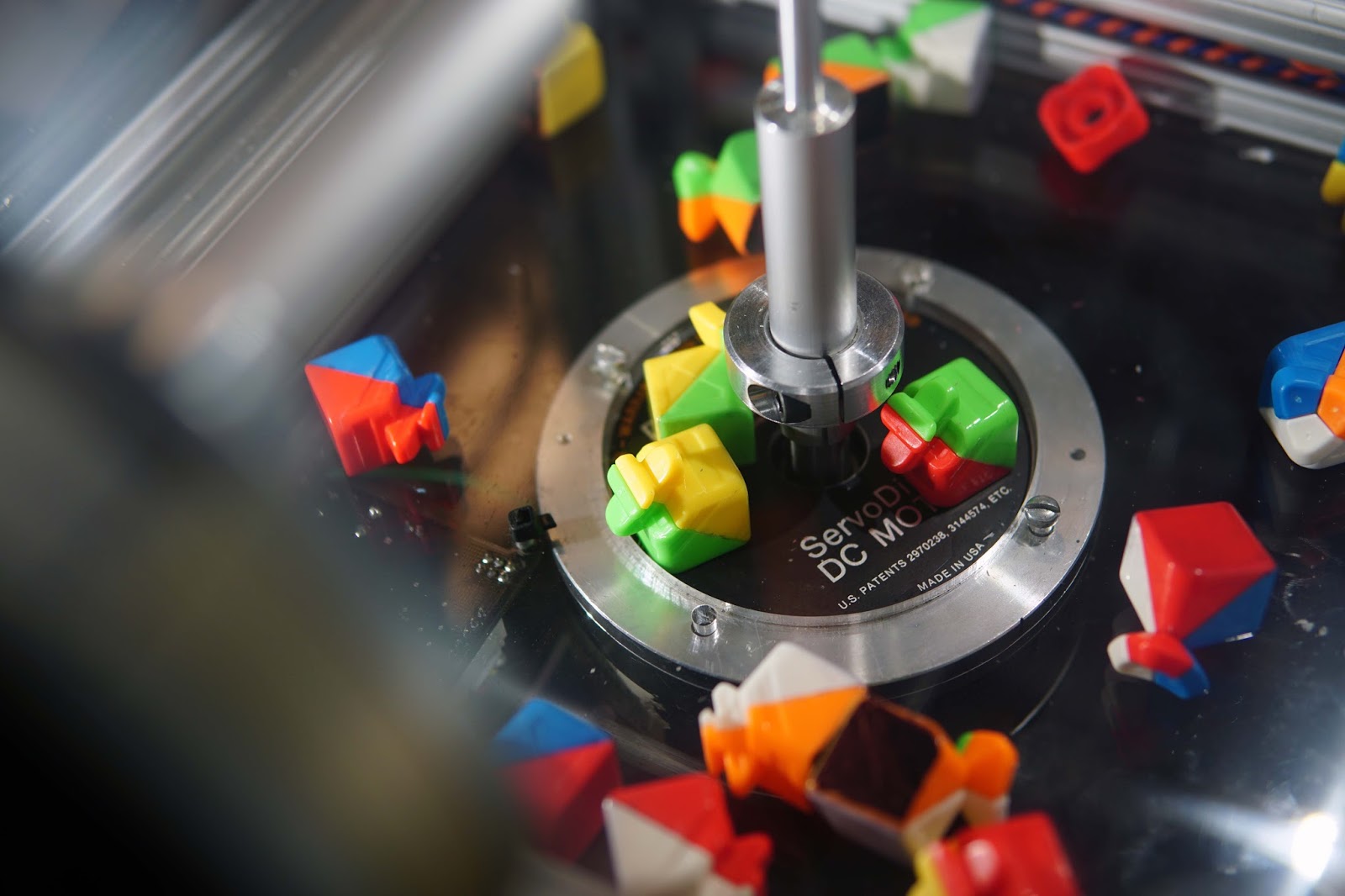
Several cubes were broken and rebuilt in the process:
Build Log
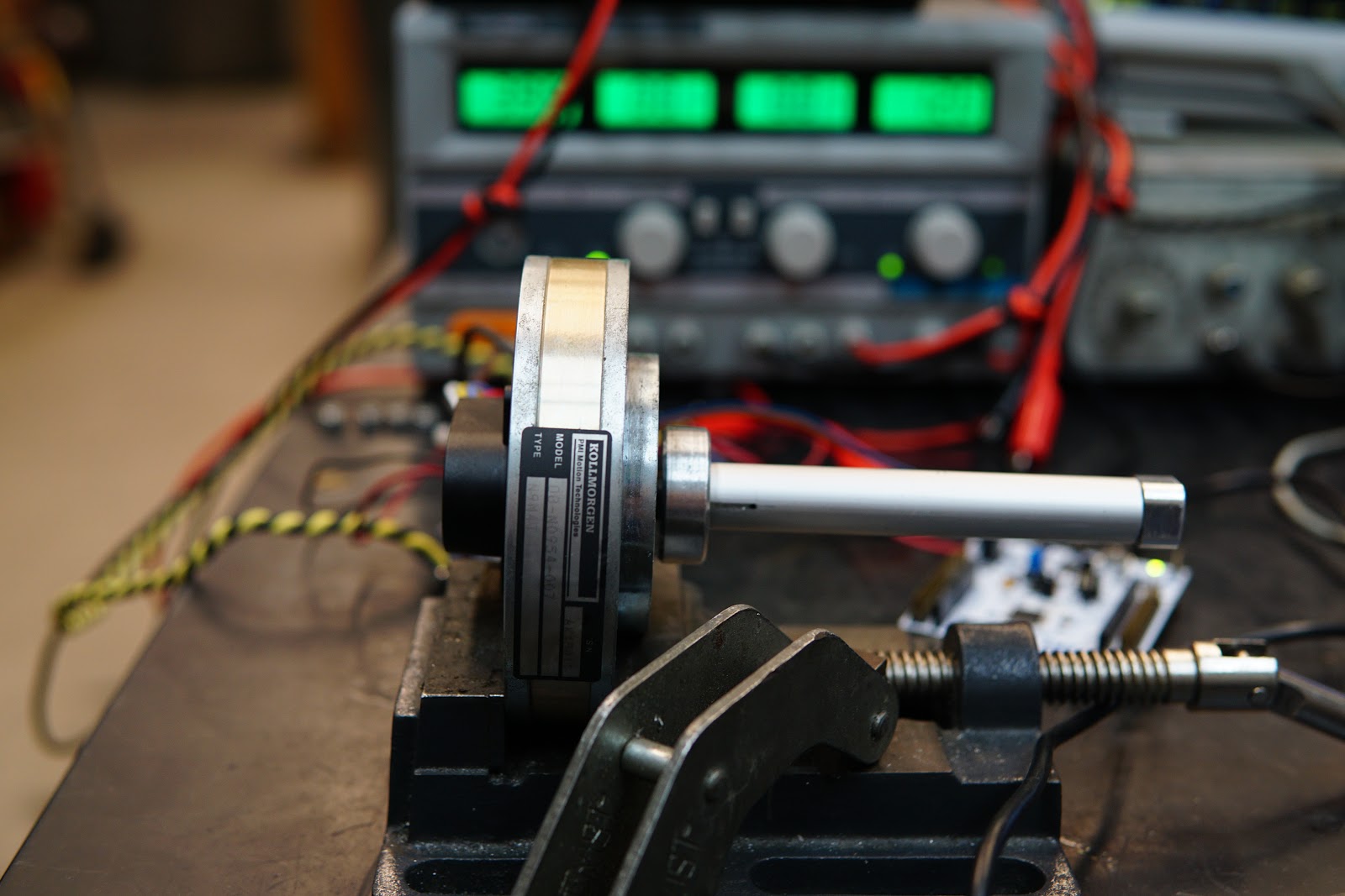
The hardware started out with a 1-axis test setup cobbled together out of spare parts. Below is a big ServoDisc U12 and cruft encoder found lying around MITERS, the motor controller I built for 6.131 a few years ago, with everything wired into a Nucleo for control. I used this setup to implement the minimum time controller in hardware, and figure out a ballpark for how fast this thing could go.

The answer was pretty darn fast.
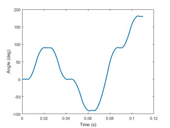
The plot shows a sequence of 90 and 180 degree moves. Each 90 degree move here took a little under 15 ms. And that was only at 40 volts.
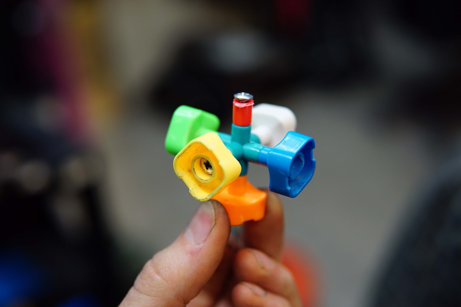
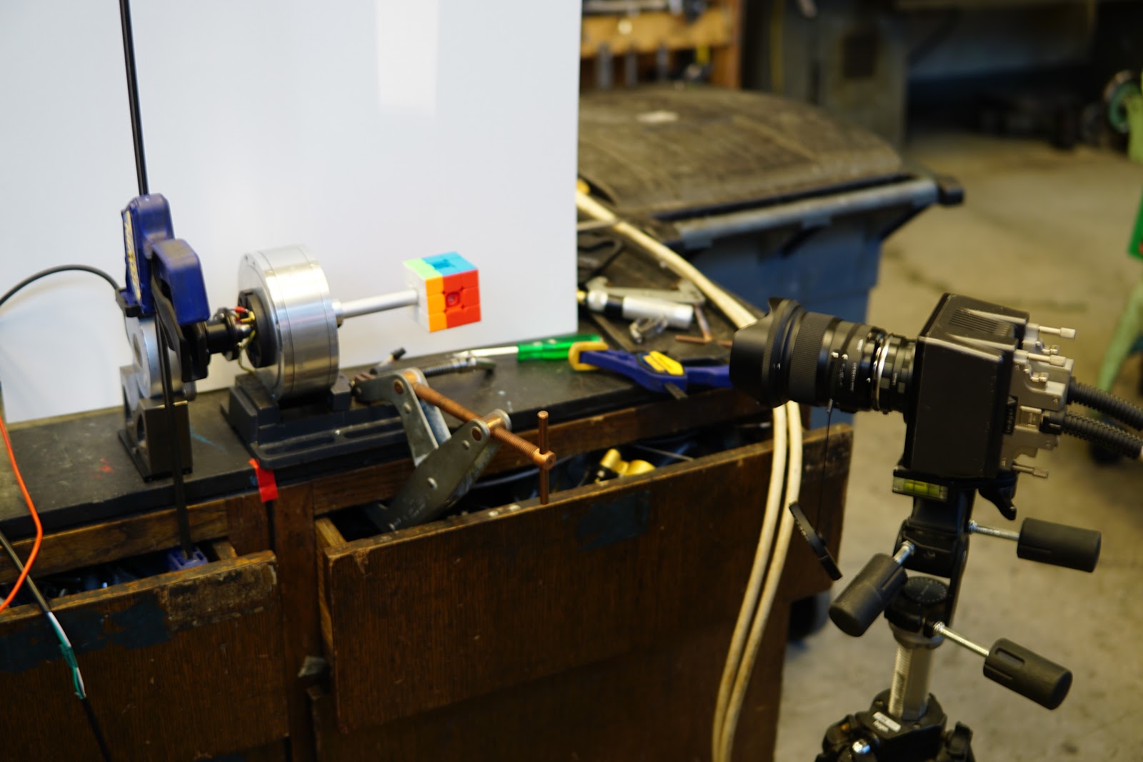
We tested with an actual cube, using Bayley's Photron for high-speed recording. The "speed cubes" we used have pop-off caps at the center of each face. Beneath the cap is a screw you can use to adjust the amount of slop in the cube. We machined some square-drives that press into the recess beneath the cap, so no cube modification was required.
One counterintuitive trick for getting things to work well was to make the cube really tight. When the cube is loose (like it would be if a person were trying to solve it fast), the outer faces just cam outwards when you try to turn the center faces quickly - see the Cubsplosion video for what this looks like. It took tightening the cube way past what intuitively felt appropriate, in order to stop the camming action from happening.
From this point, the hardware was relatively straight forward. The big ServoDisc was swapped for six smaller ones; 2 from my old robot arm, and 4 more from ebay. The smaller ones have the advantage of having higher torque-to-inertia, so should are capable of even greater angular accelerations, and draw much less power in the process. I machined a bunch of motor-to-cube couplings, and threw together a box to hold everything out of some laser cut acrylic and scavenged 80/20.
To be specific, the motors are 4 ServoDisc N9M4T motors, and 2 UD9-E's. These two motors have identical performance, but the N-ones use neodymium magnets, so they're much thinner.
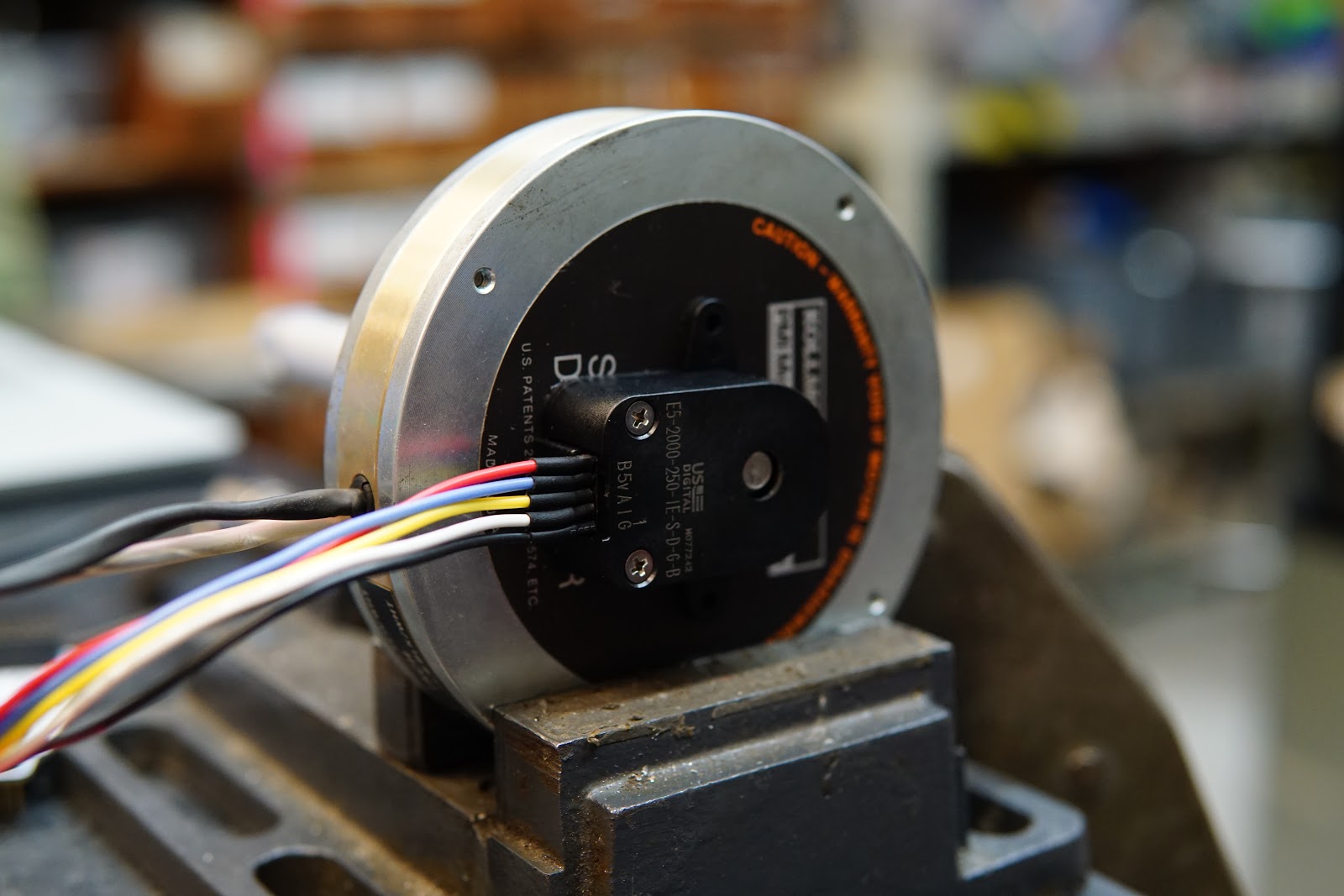
Each motor has a US Digital 2000 line optical encoder strapped on the back. While that much resolution definitely isn't necessary, we found the encoders for $14 apiece on ebay, brand new, which was an excellent deal. The encoders only had 1/4" bores through the optical discs, and none of our motors had 1/4" shafts. In fact, the N9's didn't have any shaft whatsoever protruding beyond the back of the motor. We stuck each motor in the lathe, held by the front shaft, and reamed 1/4" holes in the backs. 1/4" dowel pins were pressed into the holes, to add enough shaft to mount the encoders to. The N9's also had no features to mount the encoder sensor and housing to, so they were held on with some VHB.
I built some custom DC motor controllers to do the servo-ing:
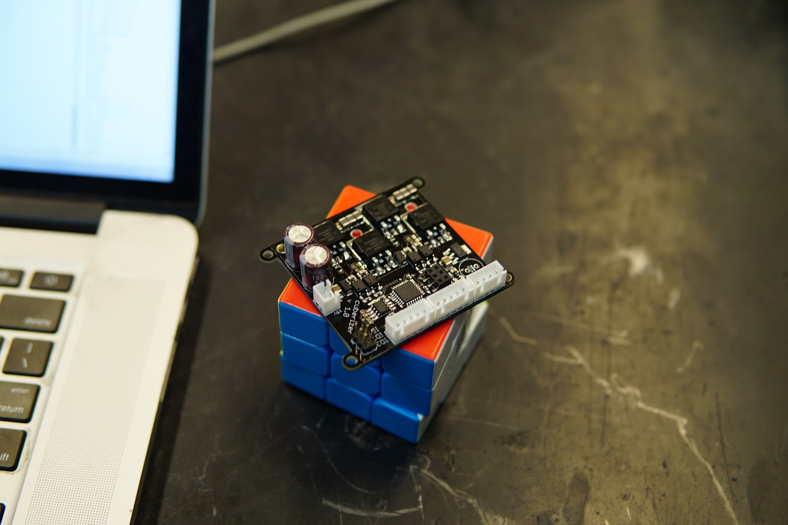
The motor controllers aren't anything too fancy - in fact, they don't even have current sensors on them. Gate drive uses and external 12V power supply and bootstrapped gate drive optoisolators. They've each got an STM32F303K8 doing all the control. Commands are sent to each controller over a differential serial interface, and there are 2 extra GPIO pins broken out, which are used for synchronization between the 6 motors. The controller is built out of 100V FETs, so I was expecting it to run up to 60V with no issues, but we've managed to blow up one of them twice at that voltage, when the cube locked up. I'm not sure if it's a conventional FET-blew-up-from-too-much-current situation, or ringing on the bus causing the FETs to avalanche and die, or something like that. It is suspicious that the same one has died twice though. I also have a set of lower-Rds(on), higher gate charge version of these FETs I could swap to, which should help on both accounts.
Here's the firmware running on them
Jared came up with an excellent system for synchronization/anti-collision between the 6 faces. On the hardware side, this consists of the AND BOARD, which, as you might expect, basically is just an AND gate (it also does the logic power distribution). Each motor controller has a digital output going to the AND BOARD, which ANDs the six signals, and a digital input driven by the output of the AND gate.
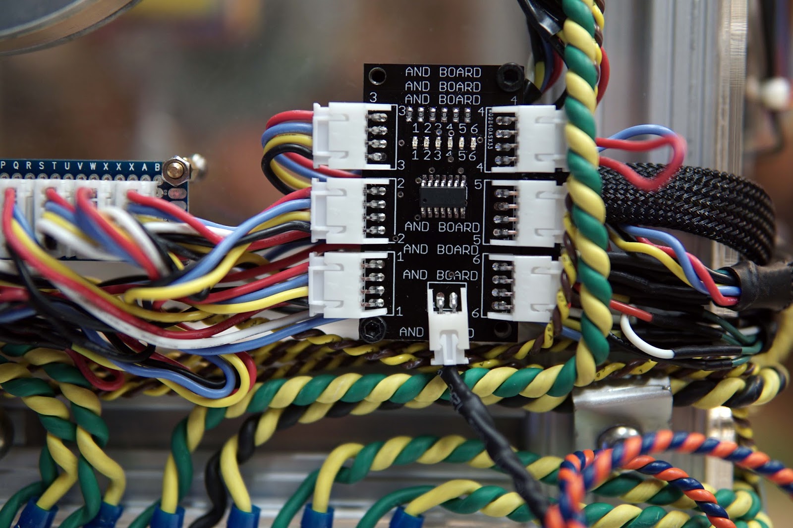
When a motor starts a move, it turns off the output of the and board, and turns it back on once it has completed the move. When none of the motors are moving, the output of the AND gate goes high, signalling to the next motor in the move sequence that it's safe to start moving.
After the solve sequence is found, the sequence of moves is sent to all the motor controllers at once over differential serial. Each motor controller has a different ID number, so they can pick out the moves corresponding to their ID number. Using the output of the AND Board to keep the count of elapsed moves, the six motor controllers step through the sequence of moves until the cube is solved.
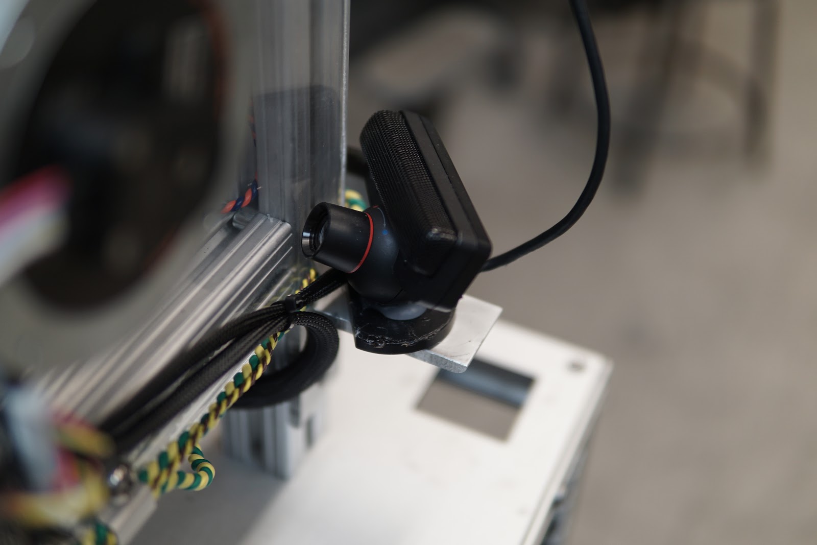
Two PlayStation Eye cameras are positioned pointing towards opposite corners of the cube, so that all 6 faces can be seen with only 2 cameras. Jared was able to get these things running at ~150 fps under Linux, and at very low latency compared to your typical webcam
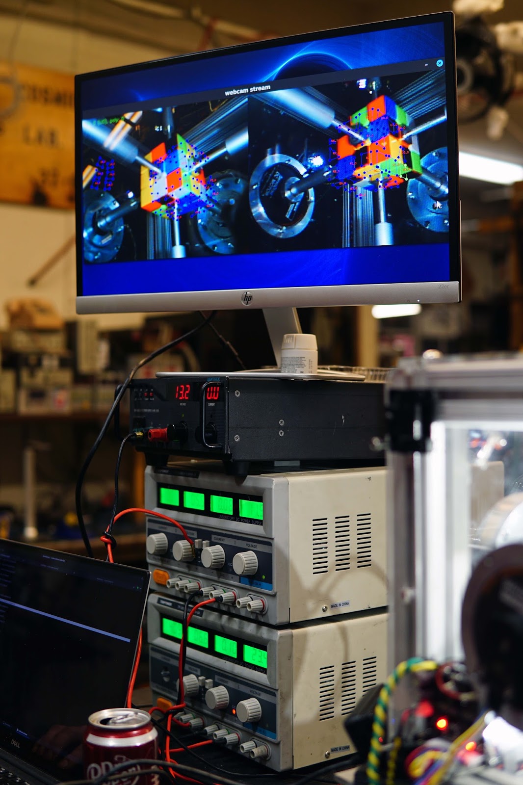
Here's part of the software stack ;)
Up top is a monitor showing the camera's views of the cubes. Jared's software allows you to draw polygons on the screen, and assign them to different faces of the cube. The pixels inside each polygon are averaged and compared to some thresholds to determine the color of each face. We found that distinguishing the red faces from the orange ones was finicky, thanks to the low-quality of the cameras, so we sharpied the orange faces black. Apparently that's allowed though.
Once the faces are identified, the solve sequence is computed using the min2phase algorithm. This returns a solution which we've observed to be 19-23 moves for a well-scrambled cube. The fastest solve we've done was actually a 21-move solve, so just getting a little lucky could easily shave off another ~30ms from the time.
And like all good projects, this thing requires a tall stack of power supplies to run - 5V logic power, 12V gate-drive power, 24V LED power, and motor power.
For consistent lighting, there's a bright LED next to each camera, lighting up the cube from the corners:
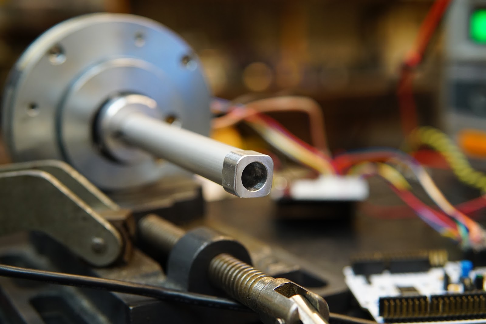
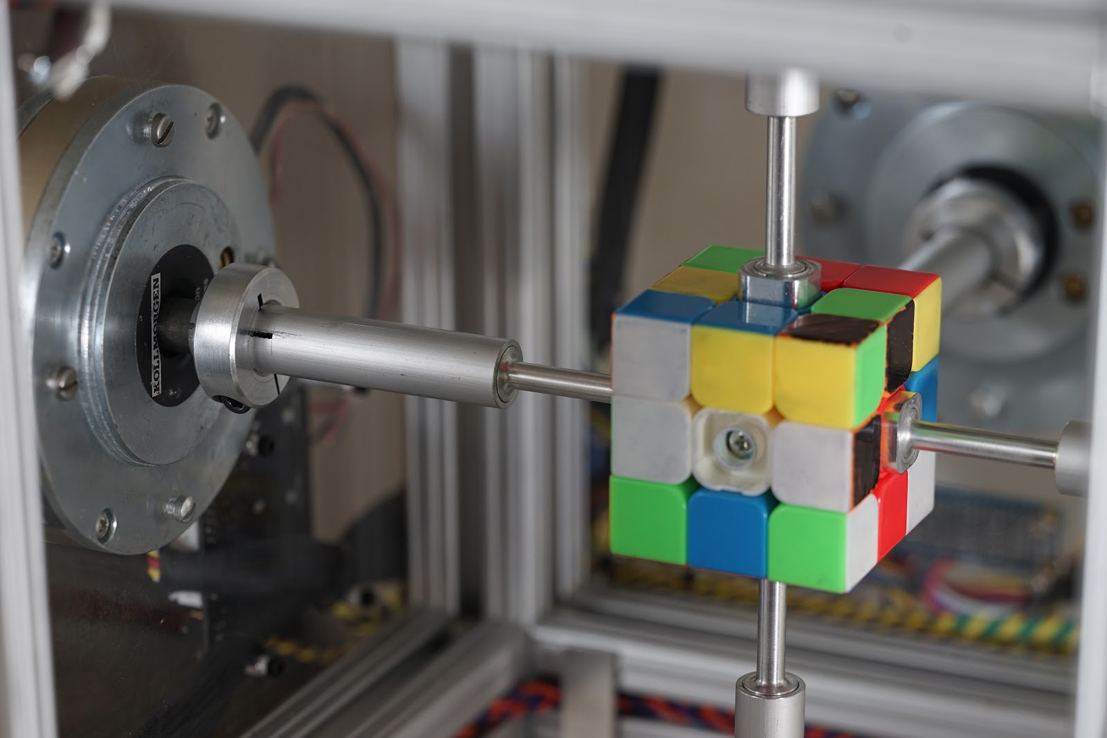
Here's a better view of how the motors interface with the cube. Popping the cap off each center face reveals an adjustment screw, and a square cavity which the shafts interface with. Each of the shafts can be loosened to slide out of the cube, so that the cube can be removed from and inserted into the box.
For added legitimacy, here's a scope shot of some signals during the fastest solve. The blue trace is one of the pins on the AND Board. When it toggles high at the end, the motor drivers think they are all done moving. From the high-speed video at the beginning of the post, you can see that the AND board actually turns on a few ms after the cube could be counted as being solved. The yellow trace is connected to the DTR pin on the USB FTDI adapter going from the computer to the motor drivers. When the solve button is pressed, the first thing the software does is toggle this pin, before even capturing the images from the webcams.

Here's another entertaining scope shot. The yellow trace is the AND board, blue is the DC bus current measured with the LEM-Stick. The purple trace is the integral of the blue trace. During this particular test, the contraption drew 6 Amp-seconds of current (i.e. 6 coulombs of charge) at 40 V, meaning that the solve took 240 Joules of energy, and peak power was ~1300 watts.

That's amazing folks, fair play to ye!
ReplyDeleteApparently there are people in the world that are far smarter than I am.
ReplyDeletei was just thinking something like you were.
DeleteNot to mention the fact of a computer knowing how to solve it so easily.
people and computers...
Apparently there are people in the world that have far more time than I have.
DeleteJooby Zat - It's a heck of a lot more relevant than most projects I worked on in college lol ; ).
DeleteSo impressive guys - I'd love to see you make the record official!
Are you using a human solve system like CFOP, roux or basic solve? Or do you brute force compute the fastest method by number of moves?
ReplyDeleteUsing min2phase. See Jared's post (link at the top). It doesn't find the optimal solve, but it does find a good one (usually between 19 and 23 moves) very quickly.
Deletevery nice, well done!
ReplyDeleteGreat Workd!
ReplyDeletewhy don't you use a shorter cables?
ReplyDeleteHey, Ben. My name is Jack Williams and I am a reporter for Caters, a newswire service based in New York. Great work on this project! We would love to write a story about it and send the piece out over our wire to the mainstream media outlets across North America and Europe. Would you or Jared mind dropping me an email to discuss, please? Thanks. jack@catersnews.com
ReplyDeleteHey Ben, amazing rig! May i ask what kind of camera you're using to take the high speed shots? We use a Sony rx10 mk3 at up to 1000fps but are always on the hunt for other options, aside from a Phantom.
ReplyDeleteA friend has a Photron ultima APX he refurbished. My lab also has the rx10, and I've found it pretty miserable to try to do high speed stuff with.
DeleteHi Ben. I'm a writer for Digital Trends. I'd love to cover this project for our readers. Would it be possible to email me on lukedormehl@gmail.com? Best wishes, Luke
ReplyDeleteDo the computed solutions ever come up with 2 opposite faces needing to be rotated in sequence?
ReplyDeleteIf yes ... they could be done at the same time to go faster but would presumably mess up the AND logic.
Yes, it occasionally does, and the machine executes both moves at the same time. If you check the slow-motion, there's a double-move early on in the sequence.
DeleteGreat project as always! It's interesting to watch it spread through the news outlets and hit trending on youtube.
ReplyDeleteHad the same exact thought when I saw the "sluggish" stepper motor versions, just never had time to get around to it.. One thing though, you are definitely aware that by using the thinner, longer type of motor you can get higher acceleration right? Happens to have some of those lying around, maybe I'll put together something really quick, someday..
I completely agree, if you're talking about the acceleration of just the motor - but it's the optimization game of total acceleration capability, including the cube inertia. Going down in radius, while increasing the torque-to-inertia, decreases the torque capability. The servodiscsc, thanks to their particular construction, hit a pretty good sweet spot. Most of the coreless pencil motors I can think of (maxon, faulaber, etc) don't come in sizes large enough to work out for rubik's cube-ing. But you if could build an arbitrarily long, arbitrarily small diameter motor (without the rotor getting too floppy), that would be the way to go.
DeleteTrue. With a guesstimated cube inertia of 150 gcm2, about 2x the acceleration at best. If you consider friction, the improvement is probably going to be marginal. The particular motor I'm talking about is the maxon 4pole from the "dynamixel pro graveyard".
DeleteAre you using diodes to prevent back EMF from the motors? I remember from my telescope building days, omitting them from the design could blow FETS.
ReplyDeleteThis comment has been removed by the author.
ReplyDeleteToo fast ! XD
ReplyDeleteBuild me the same to lace up my shoes in the morning. :P
Hello
ReplyDeleteI'm doing the same project at the University. We choose the same rubik's cube and the same mechanical shaft solution. My shaft are 3D printed.
We choose Kociemba algorithm for the resolution.
For color detection which solution did you choose ? I see that some cubies are colored in black.
Good job.
thanks, that made my day :)
ReplyDeleteGreat job!
ReplyDeleteCould you please give us some more details about the software solution? Which software did you use?
How to analyse camera images, determine the poligons and average the color inside is something i am trying to find out for a hobby project, so any hint would be welcome!
Thanks
Peter
Software details were linked to at this other blog at the top of the post:
Deletehttp://blog.cactus.zone/2018/03/rubiks-solver-software.html
Great one sir..
ReplyDeleteIn some ways, this makes it even more impressive that a human has solved a random scramble in under 5 seconds.
ReplyDeleteI am really impressed!! I hope you will do an official record, it would be worth it imo = )
ReplyDeleteThis is so freaking Fast, awesome work.
ReplyDelete
ReplyDeleteOlá amigo boa noite estou com um projeto parecido ao seu porem mais simples, você consegue me ajudar? gostaria de código para poder implementar no meu robô.
obrigado
Love the videos, especially of the cube explosion.
ReplyDeleteAs far a tuning goes, "simply" create a simulation of the system and do the tuning on that.
Would be a good project for the right advanced class...
I am guessing at least 5-10X the effort as building the real thing to get it close enough to be useful. Probably a lot slower runtime as well.
Awesome....
ReplyDeleteHi,
ReplyDeleteThis is so cool !
Would I able to introduce it as web article ?
I sent a message to you from "About" :D
Thank you for taking time.
Wow! This is great. I love it
ReplyDeleteGreat. Gathered some good knowledge. Thanks
ReplyDeleteAbsolutamente sorprendida. ¡Vaya talento!
ReplyDeleteHi there,
ReplyDeleteI am currently writin my bachelors thesis about building my own solver and since your project greatly inspired my approach i was wondering if u would let me use on of thos beautiful pictures of your solver to help describe my research process. I would of course give you credits for the pictures.
Amazing work btw
You guys really need a Captcha to keep out the spambots in your comments sections lol ; )
ReplyDeleteWow very nice
ReplyDeleteDoing some quick math based on the 1DOF graph you show, each corner of the cube experiences 176 Gs of outward acceleration! Unbelievable work, well done :)
ReplyDelete